Showing posts with label technical. Show all posts

Wednesday, January 26, 2011

Peugeot 103 Ignition coil re-winding

The Peugeot 103 models made before 1980 or so were built with a very shoddy Novi brand 2 coil stator. This stator has a major weakness in the construction and design of the ignition coil, which is poorly insulated and potted, leading to erratic performance and failure. As is common on many small power equipment engines, the high tension (secondary) stage of the coil is wound directly around the primary (lower voltage) winding all inside the flywheel. After a certain amount of figuring and experimenting, I have successfully re-wound the internal stator coil to be used in conjunction with an external high tension coil, this tutorial will explain how to do this.

The first step is to remove the flywheel. Its good to use a puller for these as they are made out of brass, and mar if you try the smack them with a hammer trick. Then remove the ignition coil itself, it will be the one on top with the light brown wrapping. Its held on with 2 7mm-head bolts.
From Blog


The coil is now hanging by two wires (plus the high tension spark plug wire), one wire is 'hot' wire going to the condenser, points, etc. The other wire is the 'ground' wire that ties into the black wire coming out the bottom of the stator plate. Both of these will need to be removed and reconnected or rewired so you can cut them off as close to the coil as possible. The high tension wire coming out of the coil can also be cut off. See where that HT wire ties into the wrapping? Yeah, moisture in there was probably part of the reason you've been having problems. On my bike, before this fix, you could see it sparking all around that shoddy joint.

You can take the removed spark plug wire and use it in your moped voodoo doll, or throw it away. You dont have a moped voodoo doll? Now is the time to make one, treat it kindly and massage in fine scented oils once a week to keep your bike running in tip-top shape.

Back to the coil. Now you are left with just the coil. At its heart this thing is just a hunk of steel with wires wrapped around it. Remember the electro-magnet from 2nd grade science class- it was probably a nail with wire wrapped around it. The coil is the same thing, only instead of using electricity to pick up paper clips, your moped is using a spinning wheel with magnets on it to create an electrical charge in the windings. Basically backwards of what you did in 2nd grade.

Basically, it works like this. The 'coil' has two parts to it, just like your electromagnet. The 'Core' which is the iron or steel chunk in the center (laminated out of sheets of steel to be more efficient) is like your nail. It is the part that becomes magnetized.

The 'windings' is/are the actual wire wrapped around the core. These conduct the electricity just like the wire wrapped around the nail in your magnet.

The four magnets in your flywheel are spinning around your coil. These magnets are oriented in the flywheel to alternate between positive and negative magnetic fields. Each time the flywheel rotates 90 degrees, the direction of the magnetic field in the core switches. When the magnetic field changes, we call that magnetic flux. For some reason the guys from ICP are still trying to figure out, magnetic flux causes an electrical current in the wire wrapped around the core. Electrons get spun around the magnetic field, and the wire develops a potential or voltage.

The amount of power in the wire has to do with several factors. First, the strength of the magnets and the strength of the field in the core. You cant usually make the magnets stronger, but you can make sure this is as strong as possible by getting the core snuggled up real close to the spinning flywheel. Second, the number of wraps of wire around the core. Each wrap contributes a tiny little bit of juice, so more wraps=more power. Finally the gauge of the wire serves as a limiting factor, you can only make as much power as the wire will allow before it melts.

So, back to our Peugeot. This guy is a little bit more complicated than your standard wire-on-a-nail coil as found in puch, minarelli, etc. The high tension coil is wound around the primary coil on the same core. We dont care about that for this article. Cut it all off.
From Puegeot


The coil is coated in some nasty epoxy-like crap, a few layers of cotton tape, two layers of wire some very thin and some thicker. There are two phenolic (a brown hard plastic-like material) retainers on the ends, be careful not to break them. I broke one and replaced it with a disc cut out of tupperware lid. I found the quickest way to get the wire off was by slicing it with a dremel, but you could unwind it or cut it with a sharp knife.

When you are done you should have something like this.
From Puegeot

If you took the inner layer of fabric tape off the core, thats ok, just wrap it with a layer of hockey tape or something similar. Fabric is preferred to plastic because it will absorb the epoxy when you go to re-pot the coil.

Now a word about magnet wire. Magnet wire is solid copper wire used for winding coils. RadioShack should have it, or better yet search out your local dungeon-esque electronics/radio/etc shop. Most areas have a place like this, forgotten by time somewhere in the Tube era, when people still fixed TV's. Build a relationship with the crumudgeonly old timer behind the counter (if you are lucky he will have thick glasses, suspenders, and a beard). When dealing with electronics like one finds on mopeds, you need someone who knows how things were done 'back in the day' to ask questions of.
If he looks like this - PAYDIRT!


Anyhow, back to the magnet wire. You're looking for 24 gauge, not because that was stock but because thats the fattest wire you can fit the necessary number of wraps on the core. The wire will come insulated with a clear-ish gold/brown or red 'varnish'. You dont want the windings to contact each other, in fact, thats probably why your old coil broke- all that hair thin wire rubbing with every engine vibration.

You will have to sand off a little on the end to solder to that tab on the core. This will be your ground. If you want to keep the stock electrical system with the brake light run from the coil, you could probably slip a little shrink wrap over this and solder it to the 'black' wire... but that system is prone to BS like having your bike not run when your bulb dies, so I prefer the hard ground.
From Puegeot


Now you will start winding the coil. This is where taking your time is worth it. Nice tight wrappings, evenly spaced, are the key.
From Puegeot


You may find it helpful to use a soft tool (something that wont scratch the insulation) to keep the windings tight.
From Puegeot


When you get to the end, make a nice sharp turn around and come right back. Its important to keep the ends square and even, because they set up the whole next layer and its easy to keep straight once it is on straight, and impossible once it gits wonky.

From Puegeot


Finally you should have something looking like this.

From Puegeot


You will want to put on about 60 feet of wire, which works out to about 5 layers. This can be a little bit more, but it doesn't need to be, probably shouldn't go much less. What you are really looking for is the resistance of the coil. This will tell you the length of the wire.

Use some tape to hold down the loose end of wire and measure from that end to the ground wire.
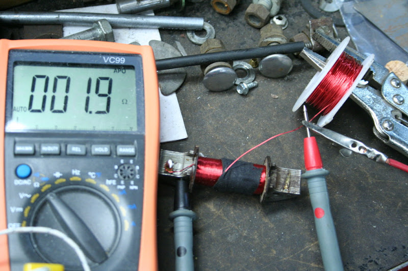
From Puegeot


You are shooting for 2 ohms. More is OK because it means more wraps, but too much could fry your points or HT coil. Try for 1.8-2.4 ohms.

Finally after winding the coil, wrap some fabric tape around the whole coil. Fabric is the best because it will absorb any potting compound and turn into a fiber-glass like hard shell to protect your electrics.
From Puegeot

Now that your coil is all wound nice and tight, you'll have to get the power out of it to the rest of your electricals. You'll be sanding off the insulation again and soldering a lead on to the loose end of the cable. You can also solder it to the stock tab if that is still in place lodged between the layers of phenolic on one of the ends... thats probably the best actually.
From Puegeot

The next step will be re-installing the coil. This will be done by running a 'hot' wire out from the soldered tab and cleaning up the stock wiring. You will also have to install the high tension coil. Since the internal coil is designed for a Bosch (puch) system, you can use the bosch coil, or you can use the generic one, or do what i did and get a minarelli/CEV/Ducati coil and the bolt holes line up with the mystery bracket on the swingarm! The new wiring diagram will look something like this:
From Blog

Now, thats a super simplified diagram. I'm going to run a 12v rectifier/regulator on mine for brake, tail and headlights, but you might want to do something different. If you saved a ground lead as seperate you can probably hook that right up to the stock black wire that is there, and get a working tail light or brake light or something.. i dunno. Try it out.

Once everything is together and working, now would be the time to go ahead and pull that coil out enough to pot it. Potting is just applying some sort of glue/varnish/etc to the wires so they dont rub on each other with engine vibration and wear the insulation off. Crazy wayne suggested fingernail polish (you could also add a nice touch of color to your stator this way- use matching shrink wrap tube!) or varnish, polyurethane, epoxy, fiberglass resin, etc. Probably anything that is heat and water impervious.

When you are all said and done, your bike should look something like this... with a nice fat ignition wire that wont get cranky in the rain:
From Puegeot coil re-wrap

Pro tip: use a little di-electric grease on the spark plug wire when you install it, and finish it with either heat-shrink tube or use the stock rubbers with a tab of silicone gasket seal inside them.

Dont forget to set your timing when you replace the flywheel!

Good luck and happy blastin'

Special thanks to Mark Hand for the excellent photographs and Michael 'mike' Naz advising/answering stupid questions.

for more discussion on coil winding:
Re-wrapping the HPI light coil
Peugeot coil winding success!

Sunday, November 22, 2009

Timing Part 1

Timing Part 1- Theory

Introduction:
Ignition timing is a frequently misunderstood and misinformed topic in the moped community. A basic understanding of the physical principles occurring in the combustion process, and the system by which the spark plug motivates this controlled combustion, will allow the tuner to adjust ignition timing to the optimal point in the combustion cycle for maximum power. This article is the first of two parts, detailing the theoretical role of ignition in the power cycle, and the implications various performance modifications have on optimal ignition timing.

To begin, lets look at the role of the spark in the combustion cycle. The ignition event occurs between the compression and power strokes. After fuel and air has been forced into a small volume and raised to a higher pressure, the spark ignites that volatile mixture and the resultant heat and pressure force the piston down to provide motive force (powahhh!!). This at the outset seems like a fairly simple proposition, but in reality there is quite a bit happening in the few milliseconds during which the piston approaches top dead center, and begins its decent.

Overview:
In reality, considering the spark and combustion of fuel as a finite event (happening all at once), is an oversimplification. The piston is traveling at such a high speed, if you were to slow things down to a comprehensible speed, the movement of the flame itself through the combustible mixture in the cylinder, would seem to happen very slowly. This ‘flame front’ speed is based on the pressure of the mixture of gasses, which is changing as the piston nears top dead center, it is also based on the fuel/air ratio, and the temperature of the gasses in the cylinder.

Going back to the cylinder now, the piston is coming up from bottom dead center, the cylinder is full of air and fuel mixed. As the piston nears the top, the points will close, breaking the flow of current through them, and diverting the electricity to the spark plug. The point at which the points ‘break’ or open, is the point used to determine timing using a timing strobe, a test lamp, or a cigarette paper. There can be a little bit of dwell downstream in the system also, from 1-3 degrees. A hotter plug will spark more readily, also a smaller gap will jump faster, so if you change these, your timing might change incrementally.

When the spark jumps across the electrode gap, the mixture, which by now should be at a very high pressure, will ignite. If the fuel mix is correct, and the piston is still traveling upwards, the flame will burn up the fuel and air mixture in the cylinder just as the piston is passing top dead center (the most powerful combustion will occur when the pressure in the cylinder is highest- e.g. top dead center), and maximum power will be achieved as the pressure from the burning gasses pushes down the piston.

Combustion theory and implications:
Now perhaps it is a bit clearer why ignition timing is so important. If the timing is off by even the slightest fraction of a millimeter, peak power won’t be achieved. This is why many people will say ‘the power is in the points’. In fact there is no power whatsoever ‘in the points’ unless they are set wrong for your particular application. Understanding the various effects modifications can have on the ignition timing, will facilitate better ‘guesstimating’ as to the optimum setting of the points. The key is the relationship between the fuel, exhaust, and temperature conditions and their contribution to flame propagation.

Flame propagation in the cylinder is a relatively simple concept when we go back to thinking of the combustion in super-slow motion. Chemistry tells us that the rate of any chemical reaction is proportionate to the initial energy. In the engine, that energy manifests itself as temperature and pressure. We assume no change in temp. We started with an initial volume of fuel/air mix and compressed it by the compression ratio to get our final pressure. Compression ratio has a huge effect on final pressure, and reaction time- read flame propagation time, but its not the only factor.

The initial amount of fuel/air in the cylinder is called volumetric efficiency, the amount of the cylinder displacement that is filled when the piston closes the exhaust port. A more efficient intake and transfer tract, along with a pipe, or the timing can all change the volumetric efficiency. Anything that increases the VE, will make the flame propagate faster, and will require ignition retard. When a pipe comes ‘on’ the powerband, it is pumping more effectively, and increasing VE. Port timing also can contribute to varying VE at different points in the powerband.

The other major contributor to flame propagation is cylinder bore diameter. For the fuel to all be burned the flame must cross the entire surface of the bore. It might seem small, but going to a larger bore requires more time to burn the fuel.

There is a delicate balance when adding performance parts or modifying your bike. Everything has the potential to change the timing, and we have very little recourse with the simple points magneto system most stock bikes have. The original design is for a relatively constant powerband between 1000-3000 rpm. Wild variations in the efficiency of various parts at various speeds can require dramatically different timings.

Common problems:
Some commonly occurring problems with timing are pretty obvious, but the small, silent loss of power at various speeds that is frequently cited by the ‘power in the points’ crowd, is something that can only be avoided by painstaking tuning. In fact, points magneto systems aren’t nearly accurate or tuneable enough to deliver peak power at all ranges, but usually a happy medium can be found that allows for good performance across a wide powerband.

Should the spark jump too soon, a condition known as detonation occurs. This is frequently referred to as ‘knocking’ or ‘pinging’ and in a highly tuned moped engine sounds a lot like a tin can full of marbles being shook. It is confusing to troubleshoot because of its sibling condition, pre-ignition, which shows up in exactly the same way. Its hard to tell the difference because they both cause the same effect, the noise you are hearing is the fuel/air mixture in the cylinder igniting before the piston reaches the top of its stroke, so the upward movement of the piston is met with a downward explosion.

In detonation conditions, the spark is jumping too soon or the flame is propagating too quickly (same thing, relatively speaking). This is why some bikes with aggressive porting or exhausts require more ignition retard than stock, or some bikes need retarded at higher speeds. As the pipe hits or the ports work more effectively, the amount of air in the cylinder (volumetric efficiency) can increase with a supercharging effect, causing the flame to travel faster throughout the cylinder.

In pre-ignition, the condition is being caused by hot surfaces inside the engine due to the wrong heat range spark plug, high cylinder temps, or too low of octane fuel for the compression. While both conditions result in the same effect, the causes are dramatically different, and the solution is as well. Due to the extreme risk of engine damage these need to be understood and correctly diagnosed.

On the other side of the coin, backfiring and power loss are telltale signs of the timing being too retarded. If the combustion occurs as the piston is already heading back down, it doesn’t take much time at all for the burning gasses to blow right out the exhaust. If this happens, the combustion only acts on the piston for a brief instant, and the piston cant harness the burning fuel. Backfiring can occur in extreme cases where the flames either blow out the exhaust, or even back down into the crankcase when the transfer ports open. Typically in cases where the timing is only very slightly retarded, the bike will have poor or no throttle response, or loose throttle response under load, but maintain it when it is on the kickstand. When there isn’t anything to push, it can rev up, but once load is applied the short amount of time the gasses push on the piston before blowing out the exhaust, isn’t enough to overcome resistance. The transfer ports can even flow backwards or stall depending on the extent of porting or the pipe.

In conclusion..
Timing need not be a mystery, or entirely guess and check. We are just starting to see the types of programmable CDI units that would allow us to dial in perfect timing, but in the meantime, the points magneto systems are perfectly workable, reliable, and offer a very simple, direct type of tuning. Having a good idea going into it about the effects other performance parts can have can facilitate easier tuning, and a better understanding of our bikes.

Thursday, November 19, 2009

Crankcase compression: theory and implications

EDIT: MAY 2014:  
This is an article I wrote 5 years ago, since then I've learned a lot and realized that primary compression is a lot more complicated in its overall effect on an engine.

I don't necessarily agree with all the comments, but I don't really have time (and still probably don't know enough) to properly discuss or refute them. At face value this is a pretty basic article describing the basic crankcase pumping operation on a two stroke. I could take it down, but it helps to remember how far I've come and how much I still have to learn, so I'll leave it, but use it at your own risk.

________________________________________________________________________


I originally wrote this for a moped army forum thread located here: http://www.mopedarmy.com/forums/discuss/7/189038/189038/

With the increase of availability of moped parts here in the U.S., we've seen a huge boom in the technical sophistication of domestic tuners. With this availability, everyone seems to be pushing the envelope further, trying to squeeze out every last iota of power from our little machines.

A good example of this is the availability of 'stuffed' cranks. Many of us have purchased them for absurdly cheap through the US moped parts sellers, having only a vague idea of what it really means to 'stuff' a crankcase, why it can produce more power, and what the implications are for the rest of the engine.

Crankcase stuffing is decreasing the volume of the crankcase to improve what is called the 'primary compression ratio'- the compression ratio for the system comprising the bottom of the piston, crankcase, and transfer ports up to the edge of the piston.

Primary compression is defined as Vi/Vf which is:
volume final divided by volume iniitial.
final volume is the displacement volume of the piston plus the volume of the case. initial volume is just the volume of the case.
when doing this for a cylinder, the head volume is relatively small, so we can achieve 11:1 (11/1 = 50cc disp + 5 cc head volume/ 5 cc head vol.) or better. When we do this same thing in the case by either increasing the displacement, or decreasing the crankcase volume (say, by stuffing the crank) we can get better compression ratios...

so what? right? why does changing the compression ratio help us?
having a higher crankcase compression ratio lets us get more air in during the intake phase, and creates higher pressure pushing that air through the transfers.
This is obvious when we go back to high school chemistry and remember PV=T(nr): Pressure times volume equals temperature, if you decrease the volume of an area, the pressure or temperature MUST increase to compensate. In the very short time that the piston is going up and down, we can assume the temp cant change much.
This makes sense for the second part, the transfer pressure. The higher pressure from a smaller final volume will push the air through the transfer ports at a higher velocity, improving scavenging, and transferring more air in the very short time the ports are open. But this only makes sense if we are getting more air in the crankcase in the first place. The displacement of the piston isn't changing, so we cant change how much air gets into the crankcase right? Wrong.

The higher ratio means that when the piston goes up and creates a vaccum in the crankcase, the vaccum is stronger. Even though transfer pressures can be as high as 50 PSI, the intake pressure pushing air through the carb and past your reeds is only 1 bar, because it is being pushed in by the atmosphere. You want to get as close to a perfect vaccuum as possible to get air to transfer as quickly as possible. (This is why piston port engines can blast reeds at the top end, the piston port has much less resistance to flow, but i digress. ) Having a compression ratio of infinity, as in 0 crankcase volume, with no leaks, would create a 'perfect' vaccuum, This would provide 32 PSI across your intake tract from the air filter in. In reality this is impossible, the ratio drops very quickly with increase in volume in the case, and the potential transfer pressure drops from 32 even faster, by PV=T. The time your piston is going up is limited by your RPMs, and the amount of air that can transfer is limited by the pressure, restrictions in the intake, and time. Therefore, if you can make more pressure (by improving the vaccuum in the case) you can get more air in the case on each stroke, which means you get more air into your cylinder, and can burn more fuel.